

I will not be posting some sprue shots as I have already made a review for this particular kit. You guys can check out the sprue shots over there.
http://modeller-innovation.blogspot.com ... 80bvd.html
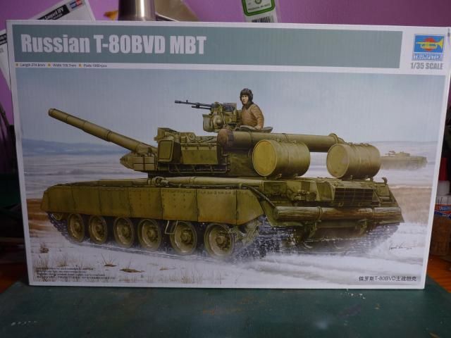
But just for the sake for it, here's the box art -
Right, so first step, the running gears. This is step 2 in the manual as I skipped step 1, which is the step for making the wheels.
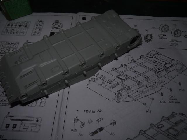
I had to put on the suspension arm swing limiters for both side in this step. Small little pieces, nothing too hard.
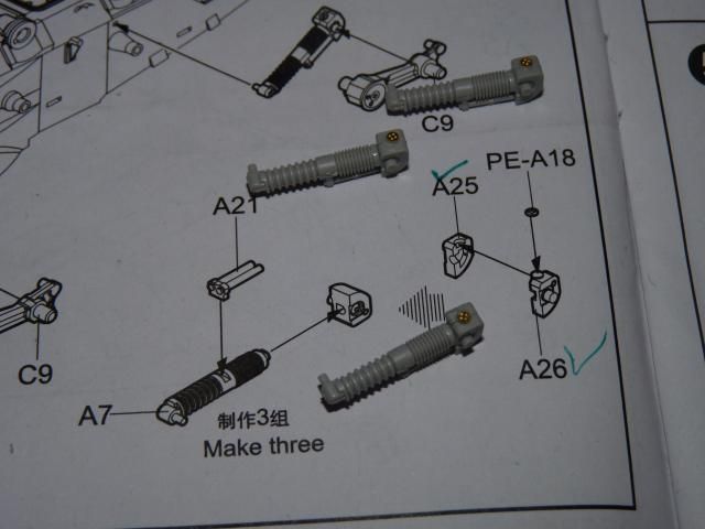
After that, I had to make 3 shocker absorbers for the left side.
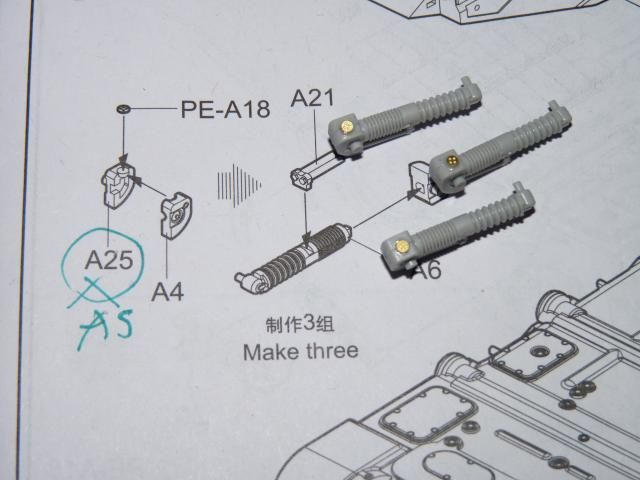
Here, I have noticed a mistake in the instructions. In stead of A25, it is actually supposed to be A5. That took me a while to figure out the correct part as I have to figure out and dry fit and match with the illustrations.
After that, I finished up step 2 by putting on those shock absorbers along with the arms and the sprocket hub.
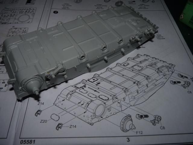
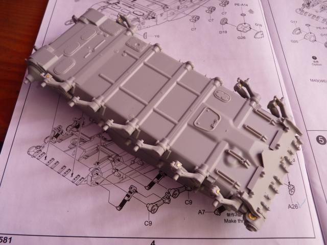
Comes step 3 and I started out with the shock absorbers for the right side. I was expecting the manual to be mis-labelled but it appears they got it right for this side.
Further along step 3; I put on the wheel arms on the left side along with some kind of hub or housing for the idler wheel.
The instruction calls for putting on the belt/holder for the unditching log but knowing full well how rough I am when it comes to handling, I decided to be come back to that later on.
I also put on the engineering blade at this point.
Coming into step 4, I put on the Sprocket hub along with the wheel arms -
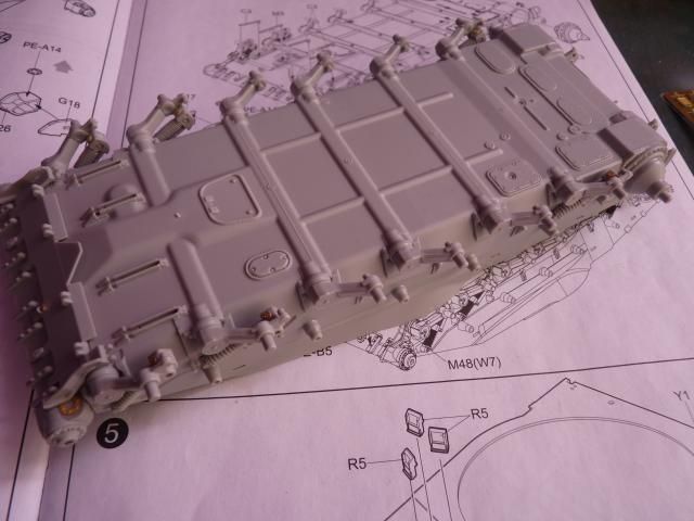
Further along into step 4, I put on the hydraulic rods for the mechanism for deploying the engineering blade.
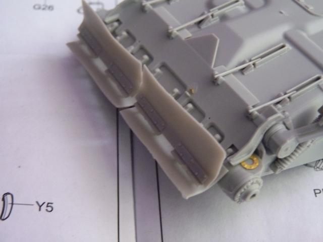
After that, I put on the last parts for step 4, where are the little rubber mud flaps that we always see underneath the T-80 series. You have an option of using rubbery material or pure plastic. I choose to go for the former as I believe their natural flexibility would mimic the real thing better than the plastic parts.
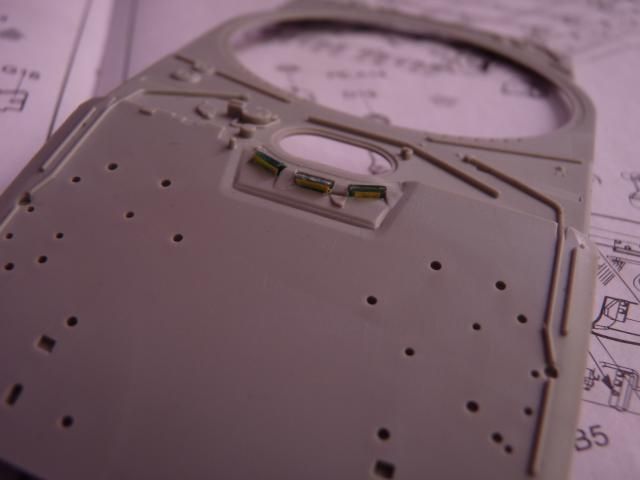
Step 5 - Time for the driver periscopes. Unfortunately, the slots are too small and I pushed the scopes into them with so much force that there were physical deformations on the periscopes area. If you look closely, you will see that deformation between the right ( our right, the vehicles' left ) and middle scope.
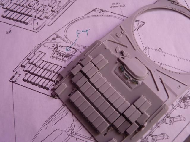
Step 6 and 7 - Although there are numerous little steps and parts involved, the ERA and some other small parts on the front glacis went on quite quickly. By the end of step 7, something funny happened. I thought the part F4 wasn't labelled at all so I wrote it down but I found that it is called out in the manual to put it on after 2 more steps. Why they even bother to show it on the manual in step 6 is beyond me. LOL.
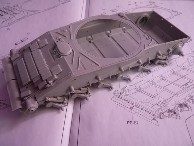
Glued the front half of the hull to the chassis and that brings us to the end of step 7. I had to use a liberal amount of glue as the fitting is kinda loose but it still sits nicely, just had to hold it down for a while.
I then put on the initial parts on the Rear Engine deck; basically just the big piece of engine mesh, the smaller mesh and another part.
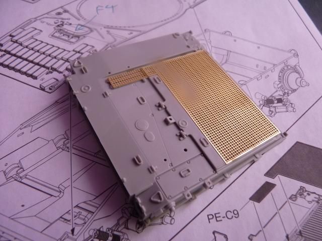
Before stopping, I delved a little into step 8 and glued on the engine deck. The way trumpeter made it, you can show the engine deck lifted up assuming that one can find the Diesel engine for the T-80UD.
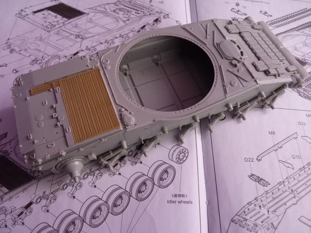
And this is it for this update. I will keep you all posted.
0 comments:
Post a Comment